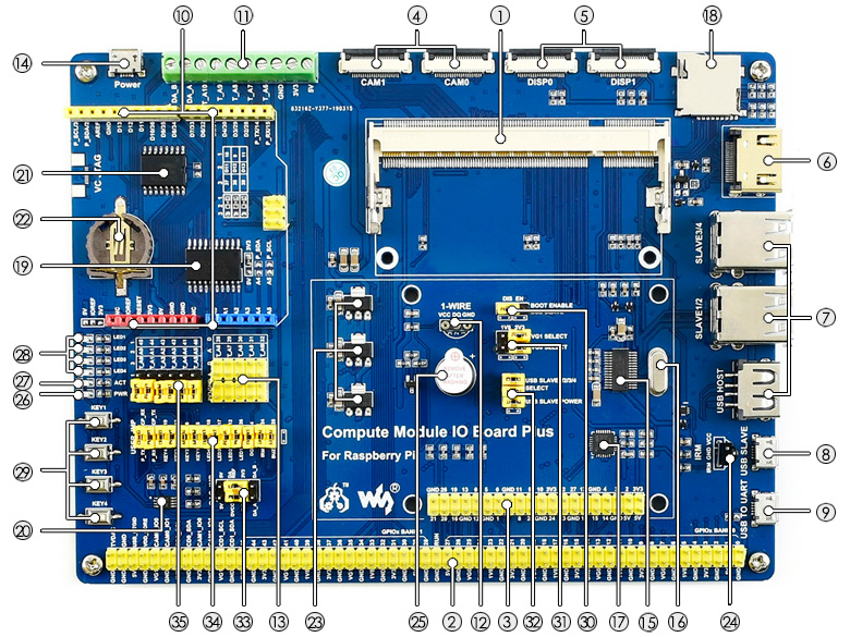
Radxa CM3S is a Rockchip RK3566 based system on module; Used with a Waveshare compute module io board plus
There are various variants with different DRAM sizes, EMMC and Wifi/bluetooth capabilities.
For the purpose of this board it’s a combination of the compute module and the Waveshare compute module IO board.
Specification:
- Rockchip Rk3566 SoC
- 4x ARM Cortex-A55
- 1/2/4/8 memory LPDDR4x
- Mali Mali-G52-2EE
- MIPI CSI 2 multiple lanes connector
- eMMC module connector
- uSD slot (up to 128GB)
- 2x USB 2.0, 2x USB 3.0
- 2x HDMI output, 1x HDMI input
- Ethernet port
- 40-pin IO header including UART, SPI, I2C and 5V DC power in
- 12V power input
This SOM is not yet generally available. The waveshare IO board can be bought via both waveshare directly and its distributors
Power control
The board can be powered via micro USB (5v, 2.5A) or via the screw terminals (11 on the overview) using the 5V/GND pins.
Low-level boot control
Serial connection on the board can be done through pins on the 40 pin GPIO header (3 on the overview), similar to a standard RPI header; With serial on pin GPIO pins 14/15. Serial specification:
- 3.3V TTL
- 1500000 8n1
Automatic maskrom mode
Rockchip Maskrom can be entered by pressing the “flash disable button” which disrupts the IO line to the eMMC.
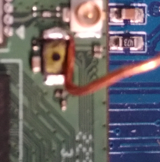
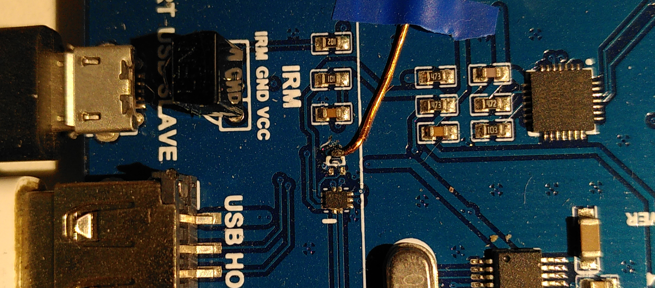
To automate this the button needs to be replaced or adapted to allow automatic switching. As this on the SOM goes to a FET the wire length doesn’t really matter. So the easiest is to add a small wire to the FET side of the button (closest to the wifi connector) which can externally be pulled to GND to switch.
As an example this hack was done to add the wire directly on top of the button, but simply replacing the button would ofcourse be valid as well:
For interacting with maskrom mode the USB OTG on the baseboard can be used, however this board only has a single USB data path which normally automatically switches to OTG mode if USB is plugged into that port. Which means we can’t use networking. To automate switching between those modes the baseboard needs some adaptations as well.
As per the schematics this switch is controlled by the Q45 FET, which can be found next to the USB host plug. Simplest for automation the easiest to just remove this FET and hooking up to what was it’s drain. Pulling that line to ground then allows automated switching to OTG mode.
To further make this viable all the jumpers on the USB hub enable block should be removed (32 on the overview) to fully disable the on-board USB hub.
Network connectivity
USB networking should be used; to be plugged into the “USB host” port.
Bootloader
TBD
Lab notes and trouble shooting
None.