Radxa CM3 is a Rockchip RK3566 based system on module; Used with a Radxa Rock 3 IO board.
There are various variants with different DRAM sizes, EMMC and Wifi/bluetooth capabilities.
For the purpose of this board it’s a combination of the compute module and the Radxa IO board.
Specification:
- Rockchip Rk3566 SoC
- 4x ARM Cortex-A55
- 1/2/4/8 memory LPDDR4x
- Mali Mali-G52-2EE
- MIPI CSI 2 multiple lanes connector
- eMMC module connector
- uSD slot (up to 128GB)
- 2x USB 2.0, 2x USB 3.0
- 2x HDMI output, 1x HDMI input
- Ethernet port
- 40-pin IO header including UART, SPI, I2C and 5V DC power in
- 12V power input
This board is available from Radxa distributors, including OkDo
Power control
The board can be powered on/off via a DC power jack:
- 12V DC input, 2.5mm x 5.5mm, center positive
Low-level boot control
Serial connection on the board can be done through pins on the 40 pin GPIO header. The board’s TX is on pin 8 and RX on pin 10 as per the pinout. GND can be connected on pin 6 for example. Serial specification:
- 3.3V TTL
- 1500000 8n1
Automatic maskrom mode
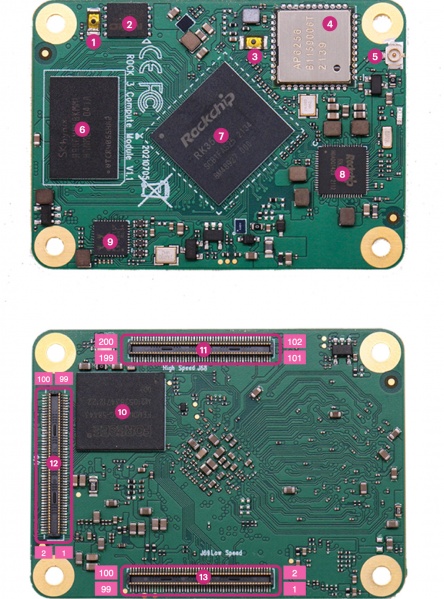
Rockchip Maskrom can be entered by pressing the “eMMC disable button” (marked as 3), which shorts the eMMC clock line to GND. GND is on the wifi chip side (marked as 4), clock input is on the opposite side.
In the Radxa schematics this button is CON2 on page 16.
To automate this the button needs to be replaced to allow automatic switching. Testing has shown that the wire lengths need to be kept very short for the trigger to work. Testing shows that directly mounting an 2N7000 mostfet in place of the switch works well (Drain connected to clock pad, Source to GND).
For interacting with maskrom mode the USB OTG on the baseboard can be used.
Network connectivity
Ethernet network is available on the IO board. Currently support by linux but not by u-boot.
Bootloader
Support with upstream u-boot; Apart from networking – TODO
Lab notes and trouble shooting
None.